Transmitters
and Link Tuners Used For Private Radio Broadcasting in the UK...PLUS..
a so called professional job from Dave!!!
large file..please be patient..it's
fun
![]()
--------------------------------------------------------------------------------------------------
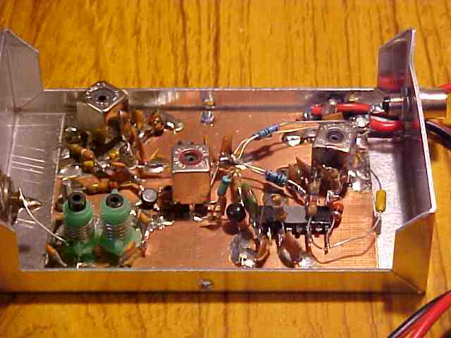
50 watt transmitter from a Private Radio Station in the UK.
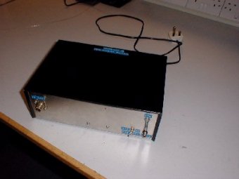
Exterior view showing enclosure. Durable construction augments uncluttered front panel layout.
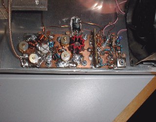
Interior parts and layout found in the transmitter are ugly but fully
functional copper clad 'spider wire' construction, with plenty of solder.
This is the driver board showing the Oscillator to the right, pre-drive
in the middle and the driver output to the left. Conventional input
and output matching is used with trimmer capacitors used to maximize
the power output. The coax output lead goes to the 50 watt amplifier output
stage, coming up next.
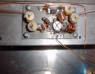
This is the 50 watt amplifier section of the transmitter. Very basic
but serviceable. It does not bother with a low pass output filter, damping
resistors or stabilization of the output device against self oscillation,
so costs are cut to the minimum. This amplifier will have good gain,
but it may well be prone to the problems highlighted in our workshop
article on amplifier stability.
-----------------------------------------------------------------------------------------
A Band 1 Link Tuner From a UK Private Radio Station.
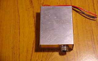
Compact 60 MHz Band 1 Link receive FM Tuner in small aluminum
case.
This receives a signal from a Link Transmitter, in the Radio
Station
Studio, some distance away. This type of radio tuner is called
'optimised'. This means that it is optimised to receive one frequency
only, i.e. narrowband. This is the cheapest way to make a sensitive, yet
selective tuner.
Inside View
The Band I Link Tuner interior showing copper clad construction and
surface mounted components. This type of build is known as 'ugly bug'
or 'spider wiring'. No printed circuit boards (PCB) are used in this
model. Whilst the layout does not look as pretty as a PCB design , groundplane
is abundant and I have seen PCB layout tuners whose performance would
be shamed by the specs obtainable with this unit. The incoming studio
signal at 60 MHz enters from the left hand aerial socket and is band
pass filtered by the two tuned circuits (green variable inductors).
At the top left is the local oscillator which runs at 49.3 MHz. The
60 MHz signal frequency and the 49.3 MHz are mixed in the dual gate
fet (a quality low noise device) and the difference signal of 10.7 MHz
is selected with the red rim toko inductor (centre of picture). This
10.7 MHz is the Intermediate Frequency (IF) and proceeds through a transistor
amplifier and is sharply filtered with a ceramic filter of 280 KHz bandwidth.
The 10.7 MHz signal, now filtered to avoid interference from other channels,
goes into the IC, which is a CA3189 fm limiter/quadrature demodulator
chip. This IC amplifies the 10.7 MHz IF signal by around 30 dB (1000
times) in it's internal limiting amplifiers, stripping off any unwanted
amplitude interference and spikes. The amplified and limited high level
10.7 MHz IF (with the FM modulation) is then applied to the quadrature
FM detection circuit within the IC (and also the 90 degree phase shift
inductor on the right). From here, the original studio audio should
emerge from the IC and is fed to the right hand phono socket. This feeds
the main transmitter, shown further up this page.
-----------------------------------------------------------------
Whilst everything above here has been constructed by
enterprising young individuals who are not boastful RF engineers, the
shambles below was constructed by a so called professional RF engineer
popularly known as 'Arsehole Dave'
who is particularly keen on quality(?). You may know him, he used to
post messages on Alt.Radio.Pirate and his motto is:
"I have been an RF design engineer for longer than I can remember,
so am probably just as thick now as when I started, so I am the weak
link in the design of this unit ;-)"
Well, He said it! Please read on...
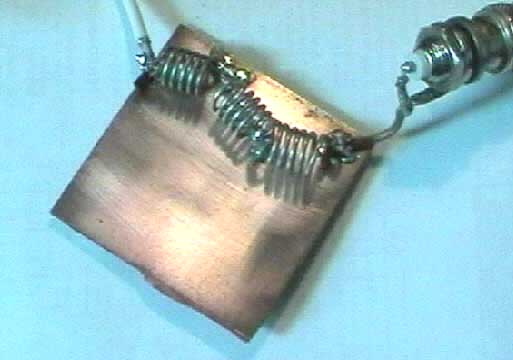
Low Pass Filter with cut off at aprox 120 MHz
This is Dave's recommended layout for a finished product, a VHF low pass filter. As you can see, the connectors are airborne and the unit looks a complete mess. He is very choosy about his connectors though, saying that industry standard SO239 is 'Rubbish'! I have been told that the above workmanship is typical of his standards. Whilst this type of thing can obviously raise a laugh or two, do not under any circumstances operate a radio station with equipment build quality down to this low standard!
Now, the above filter was built to suppress the harmonic output of the RF Power Amplifier below.
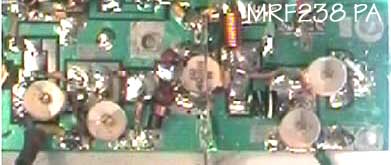
MRF 238 RF Power Amplifier
Designed for an input of 3.5 watts to deliver 25
watts output on a 13.8v dc supply at 3 amps
This looks better! But unfortunately, Dave has got all the component
values wrong in the output matching circuit, and the whole amplifier
suffers from a lack of 'damping' so self oscillations are very likely
to occur. Dave in his wisdom recommended this circuit and layout to
a novice builder and encouraged him to broadcast night and day to test
it. As expected, the circuit burst into oscillations. Which could be
a major source of interference. It has to be pointed out that Dave did
recommend this circuit as one to get maximum gain, but did not warn
the user of the potential unstable nature of such an amplifier.
In conclusion, the privateers often can turn out a better job than some boastful "professionals".